• Welcome to H4O! For a reduced ad experience, please login or register with the forum.

What did you do with your H3 recently? NEW

JPaul

Well-Known Member
Messages
2,436
Location
Way up north, UT
Now I can see where it looks like it is welded, but completely different weld then the rest of the mount. Could it chitty import steel that stressed too much being cold bent?

Watch ABNTROOP's video, those are a new set from Schwaartzy, not a repaired set. Seems some point after 2013 and before October 2015 he stopped using a one piece bent bracket and went to a two piece that is welded together but from what I can tell he didn't tell anyone that. If it was a manufacturing defect he should have refused the product and had the shop make new ones that weren't broken.
 

Schwarttzy

Sponsor
Messages
1,390
Location
Rockford IL
Hello dear friends !

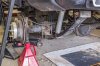
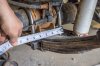
As you know, 2 years ago i bought and installed hi clearance tuned leaf spring mounts by Schwarttzy.. two week ago i go goose hunting on my hummer h3. it is 700 km serious off-road where no one lives. after 400 km i have noticed that my leaf spring mount BROKEN IN HALF ! Thank god i have sattelite phone and i can call for help !

here is a photo. as you can see it was NOT welded well ! So i live 3 days in car waited for my friend with power source and weld apparatus. He come to me and weld this mount, so i can continue my way for hunting...

I need answers from Schwarttzy ! i paid a lot of money for that spring mounts. my life was in danger because i can not move with this fault... no one around me in 400 km.. i have a lot of spare parts with me, but i did not think that leaf mounts can broke !

if anyone know how to write to Schwarttzy directly please let me know.. thank you.

Maybe the website page labeled "Contact Me" https://schwarttzy.com/contact-me/ is a more appropriate page than here for something like this.

Unfortunately that is why I never bought anything from him. His welds all look like garbage, you have very little penetration there for something that is supposed to support the weight of a vehicle.

Well, that may be true in the past. I pay professional welders that work with General Motors now.

No ! they welded .. look on picture please - so you can see weld only on top of mount.. no weld on back side where spring ... moun broken in half on bad weld.. look on picture..

I can assure you it is not my part if it's welded.


I agree. I wasn’t all that happy with the rock sliders and skid plates I bought. I had to grind off a lot of extra weld and the skid plates had a very strange mounting system.

All of those problems have been addressed with all my current parts. I pay professional welders, and the skid plates just use 5 factory bolts, and 3 holes need to be drilled for a standard nut and bolt design.


So there's definitely something odd going on here.

Something isn't right, because nowhere in that thread did I see anything showing or indicating that he switched to a two piece for the main bracket.

All of my parts are bent, I don't know what's going on there.
 
Last edited:

Acer4LO

Well-Known Member
Messages
801
Location
Illinois
I bought a set of leaf spring mounts and extended shackles back in January. Can confirm that Schwarttzy's current design is one piece.


i-MRpx7DW-X3.jpg
 

JPaul

Well-Known Member
Messages
2,436
Location
Way up north, UT
All of my parts are bent, I don't know what's going on there.

Schwarttzy, if that is the case then instead of insisting it's not your part if it is welded and apparently calling the matter closed, you should reach out to ABNTROOP at the least since his video I linked clearly shows the weld in that same exact location that lsv's broke. There is no mistaking that either of those were welded together instead of being a single bent unit. RamRod's pictures also strongly suggest his are welded as well since you can see the bleed through from the weld, and I think they are from around the same time. I'm not familiar with your manufacturing process or when you changed any of it, but if you're having the parts cut and formed and then sent directly to the people welding them up, and if you're not inspecting each unit afterwards, then it's quite possible that something was/is being done wrong during the process and either the shop wasn't bending them correctly or out of one piece and was welding them together themselves, or who knows what. But there are definitely pieces out there that have been welded together instead of being bent from one piece from what I can see.

Watch ABNTROOP's video, you can see the weld plain as day. And look at RamRod's photo I linked to as well, that too clearly shows it being a welded two piece instead of a bent one piece. If either of those were a bent one piece you'd see the inside radius instead of a sharp 90 degree angle (since 1/4" does NOT bend tight enough to form a sharp 90 inside corner unless you hot stamp it with an awful lot of pressure), and the outside radius of the bend would be nice and smooth just like the other side whereas on ABNTROOP's video you can clearly see the weld puddles.

If you didn't do that yourself, then someone in your manufacturing chain did and you weren't/aren't aware of it. Either way it is something that happened and I recommend you dig into it further before anyone else suffers a failure. Even with a really good weld, in such a high stress area it's not improbably for the weld to end up failing, or the parent material around it, due to fatigue.
 

JPaul

Well-Known Member
Messages
2,436
Location
Way up north, UT
I bought a set of leaf spring mounts and extended shackles back in January. Can confirm that Schwarttzy's current design is one piece.


i-MRpx7DW-X3.jpg

Those inside corners for the bend we've been discussing look awfully sharp for 1/4" cold bent plate steel. Can you take a picture of the profile (facing the end) of the bracket and another picture of the other side of the brackets, and then another pic showing the inside bend on the other side (in this pic you can't see it because of how you have the brackets angled)?
 

awjohnson2

Member
Messages
13
Location
Atlanta, Ga, USA
Drop down pretty much most of my drive train to track an engine oil leak...I basically pinned it to be q bad engine crankshaft rear seal...but I can seem to find the original GM part for it. I have this number from the seal itself I pulled but it comes up as a Ford f250 seal (12579715). I also found this other part number (BS 40705) which looks like what I need but isn't made by ac delco...anyone has encounter this issue before with their engines.
0ed12845a7662e644e8314fc8244adc9.jpg
417e115684ee2be34718ea5c787bb238.jpg
4aa370fa757a070f863c3d6ceaf00d4d.jpg
ac1a7ab6e3abf8f2cf6bea223af06bbf.jpg


Sent from my SM-G955U using Tapatalk


This may help..

[h=3]2008 Hummer H3 L5-3.7L[/h]
Vehicle » Engine, Cooling and Exhaust » Engine » Crankshaft Seal Retainer » Parts Information
Parts InformationOEM Part #Price
Crankshaft Seal Retainer
35 - Rear Main Seal Retainer
12579713$87.64


awjohnson2

Member
Messages
13
Location
Atlanta, Ga, USA
[h=3]2008 Hummer H3 L5-3.7L[/h]
Vehicle » Engine, Cooling and Exhaust » Engine » Crankshaft Seal Retainer » Service and Repair

  • SERVICE AND REPAIR

Crankshaft Rear Oil Seal and Housing Replacement

Tools Required


  • J 8092 Driver Handle
  • J 44215 Rear Seal Installer
Removal Procedure


126002447


  1. Remove the flywheel. Refer to Engine Flywheel Replacement (with Automatic Transmission) (See: Transmission and Drivetrain\Flex Plate\Service and Repair)Engine Flywheel Replacement (with Manual Transmission) (See: Transmission and Drivetrain\Flywheel\Service and Repair) .
  2. Remove the 2 bolts securing the oil pan to the crankshaft rear oil seal housing.
  3. Remove the crankshaft rear oil seal housing bolts.
  4. Install 2 bolts into the threaded holes to act as jack screws and tighten evenly to separate the crankshaft rear oil seal housing from the engine block and oil pan.
  5. Remove the crankshaft rear oil seal housing.
  6. Remove the 2 bolts from the jack screw holes.
126002448


Important: Do not damage the seal bore.


  1. Using a hammer and a punch, remove and discard the crankshaft rear oil seal.
  2. Clean and inspect the crankshaft rear oil seal housing.
  3. Clean and inspect the engine block and oil pan sealing surface.
Installation Procedure


126002449


Important: The crankshaft rear oil seal housing must be installed within 10 minutes from when the sealer was applied.


  1. Apply a 3 mm (0.12 in) bead of sealer to the following:

    • The crankshaft rear oil seal housing, were the housing meets the engine block
    • The surface of the crankshaft rear oil seal housing, were the housing meets the oil pan
    • The surface of the oil pan, were the oil pan meets the housing Refer to Adhesives, Fluids, Lubricants, and Sealers (See: Specifications\Sealers, Adhesives, and Lubricants) .
126002447


Important: Tilting the crankshaft rear oil seal housing will allow sealer between the housing and the oil pan.


  1. Complete the following to install the crankshaft rear oil seal housing:

  1. Align the housing with the right alignment dowel, tilting the left side up slightly.
  2. Align the housing with the left alignment dowel.
  3. Press the housing against the engine block into place.

  1. Install the crankshaft rear oil seal housing bolts.
Notice: Refer to Fastener Notice (See: Service Precautions\Vehicle Damage Warnings\Fastener Notice) .


  1. Install the 2 oil pan bolts.

    • Tighten the crankshaft rear oil seal housing bolts to 10 N.m (89 lb in).
    • Tighten the (end) oil pan bolts to 10 N.m (89 lb in).

  1. Lightly lubricate the crankshaft rear oil seal lip with clean engine oil.
  2. Position the plastic installation sleeve supplied with the new seal to the crankshaft.
126002450


  1. Using the J 44215 with the J 8092 and a hammer, install the crankshaft rear oil seal into the crankshaft rear oil seal housing.

    • The spring side of the seal goes toward the engine.
    • Ensure the seal is installed square.
    • The seal will bottom out in the housing when fully installed.

  1. Install the flywheel. Refer to Engine Flywheel Replacement (with Automatic Transmission) (See: Transmission and Drivetrain\Flex Plate\Service and Repair)Engine Flywheel Replacement (with Manual Transmission) (See: Transmission and Drivetrain\Flywheel\Service and Repair) .


© 2018 ALLDATA LLC. All rights reserved. Terms and Conditions
 

awjohnson2

Member
Messages
13
Location
Atlanta, Ga, USA
Or this..
[h=3]2008 Hummer H3 L5-3.7L[/h]
Vehicle » Engine, Cooling and Exhaust » Engine » Rear Crankshaft Main Bearing Seal » Parts Information
Parts InformationOEM Part #Price
Rear Crankshaft Main Bearing Seal
34 - Rear Main Seal
89018205$26.23


[h=3]2008 Hummer H3 L5-3.7L[/h]
Vehicle » Engine, Cooling and Exhaust » Engine » Rear Crankshaft Main Bearing Seal » Service and Repair » Crankshaft Rear Oil Seal Replacement

  • CRANKSHAFT REAR OIL SEAL REPLACEMENT

Crankshaft Rear Oil Seal Replacement

Tools Required


  • J 8092 Driver Handle
  • J 44215 Rear Seal Installer
Removal Procedure


  1. Remove the flywheel. Refer to Engine Flywheel Replacement (with Automatic Transmission) (See: Transmission and Drivetrain\Flex Plate\Service and Repair)Engine Flywheel Replacement (with Manual Transmission) (See: Transmission and Drivetrain\Flywheel\Service and Repair) .
126002448


Important: Do not damage the crankshaft or seal bore.


  1. Using a suitable tool, pry the crankshaft rear oil seal out from the crankshaft rear oil seal housing. Discard the seal.
Installation Procedure


  1. Lightly lubricate the crankshaft rear oil seal lip with clean engine oil.
  2. Position the plastic installation sleeve supplied with the NEW seal to the crankshaft.
126002450


  1. Using the J 44215 with the J 8092 and a hammer, install the crankshaft rear oil seal into the crankshaft rear oil seal housing.

    • The spring side of the seal goes toward the engine.
    • Ensure the seal is installed square.
    • The seal will bottom out in the housing when fully installed.

  1. Install the flywheel. Refer to Engine Flywheel Replacement (with Automatic Transmission) (See: Transmission and Drivetrain\Flex Plate\Service and Repair)Engine Flywheel Replacement (with Manual Transmission) (See: Transmission and Drivetrain\Flywheel\Service and Repair) .


© 2018 ALLDATA LLC. All rights reserved. Terms and Conditions
 

Panzer07

Well-Known Member
Messages
2,548
Location
Ontario, CA
Last edited:

Bowser-II

Well-Known Member
Messages
270
Location
Hagerstown, Maryland
Those inside corners for the bend we've been discussing look awfully sharp for 1/4" cold bent plate steel. Can you take a picture of the profile (facing the end) of the bracket and another picture of the other side of the brackets, and then another pic showing the inside bend on the other side (in this pic you can't see it because of how you have the brackets angled)?

When I got mine I thought the insides bend we're rather sharp, and though I didn't strip the paint to verify the outer radius looked like a bend and not a weld. They are about 18 months old, I think I'm going to take a deeper look at them tonight.


Sent from my iPhone using Tapatalk
 

4speedfunk

Well-Known Member
Messages
4,250
Location
Tardville
his video I linked clearly shows the weld in that same exact location that lsv's broke.

Yeah I do see the weld. That being said, Schwarttzy is a straight shooter...I'm sure he will take care of the situation. Nobody ever learned a damn thing by succeeding. Improvement comes from failure...not success. Lets not throw a rope over a tree limb just yet.

In regards to forming cold steel, there are lots of tables and charts on the internet for "RECOMMENDED bend radius" and also "MINIMUM bend radius" for 90 degree bends in various materials. Note that there are two categories...RECOMMENDED and MINIMUM. All qualified press-brake operators are aware of these industry standards, and sometimes they even have them posted on the machine. On something like this...the recommended inside bend radius is typically 1.5 x t ("t" being the material thickness). So for .250" wall material the recommended inside bend radius would be .375" or 3/8". Obviously that is a rather large radius, and it would definitely effect the fitment of the part. Clearly a tighter radius fits better but, once you go past the RECOMMENDED bend radius...it becomes a judgement call from the designer. What is part used for? What stresses will it see? What is it's tendency for corrosion at the bend?

I make lots of formed pieces, and I routinely exceed the recommended radius. But, they are not critical suspension parts subject to high stresses or vibrations. So perhaps in the case of these leaf spring plates, a larger radius should be used? A 3/8" inside radius puts the upright surfaces further away from the sides of the leaf spring pack. However, considering the "clamping" action of the u-bolts, I'm not so sure the sides of the leaf spring plates need to be tight up against the sides of the leafs. After all...the thing will be clamped very tightly, so there should be no movement whatsoever, after it is tightened. So would a larger (stronger) radius effect the fitment that much?

Here's a great article if you like to geek-out on this exact subject...
https://forum.solidworks.com/thread/211698
 
Last edited:

Acer4LO

Well-Known Member
Messages
801
Location
Illinois
Those inside corners for the bend we've been discussing look awfully sharp for 1/4" cold bent plate steel. Can you take a picture of the profile (facing the end) of the bracket and another picture of the other side of the brackets, and then another pic showing the inside bend on the other side (in this pic you can't see it because of how you have the brackets angled)?

I am away for work rn to take new pics, but I took a few when installing it, so this will give the idea:

i-zksdzfD-X3.jpg

i-TwHQKz3-X3.jpg

i-4BkFvPX-X3.jpg
 

JPaul

Well-Known Member
Messages
2,436
Location
Way up north, UT
Not out to lynch him or anything, reading through his other thread and the iterations and feedback he welcomed I'd expect him to back up his product and if it was due to an oversight on his part (such as if it's something happening during the manufacturing process and he wasn't aware of it) then digging into the matter and finding out why at least several of his brackets have ended up being welded together instead of a single formed piece. But his comments in the absolute that if it's welded it's not his and not knowing how they could have ended up that way without making absolutely sure are a bit concerning to me personally. A better response would have been to acknowledge that while they are supposed to be a solid piece there might be an issue during manufacturing he does not know about and that he will look into it. Seems like right now he's a bit hot under the collar about it.

Schwarttzy standing over there like "I'm right here guys! I can hear what you're saying!!"
:giggle:


Acer4Lo, thanks. It is interesting, the left bracket in the top pic looks like it is a one piece formed like it should be, but the one on the right still really looks like it was welded together, that inside corner is super sharp looking compared the to the rest of it. Maybe they are breaking during the bending process and they are being welded together by the shop?
 

lsv_palana

Well-Known Member
Messages
383
Location
Kamchatka, Russia
Schwarttzy says:

I can assure you it is not my part if it's welded.


WHAT ? YOU SEND ME THIS PART in the box ! I dont know where did you take it, but you send it to me for 250dollars plus shiping .. near one year ago i send you a message where shows you that something wrong with these mounts because they bented (with photos). you say to me that i overtight u-bolts.. but i use special tool for that and not overtight these u-bolt..

as you can see i risked by my life using your mounts ! i think at least one of them was not good.. i prefer to get new one from you .. thank you.

and by the way.. i send you a message on page "contact me" on your site.. no answer.

Отправлено с моего SM-N950F через Tapatalk
 

Acer4LO

Well-Known Member
Messages
801
Location
Illinois
It is interesting, the left bracket in the top pic looks like it is a one piece formed like it should be, but the one on the right still really looks like it was welded together, that inside corner is super sharp looking compared the to the rest of it. Maybe they are breaking during the bending process and they are being welded together by the shop?

Thats what I was thinking. Maybe the machinist at the shop Schwarttzy used in 2015ish was unaware what this part was being used for and thought it would be okay to weld it? Not saying the shop didn't know what the part was for, but the actual person fabbing this these mounts. Also I am not sure Schwarttzy had the ability to check every single one for quality control. I know when I ordered mine he was in Australia for work, so I messaged him and he said the shop that made them would send them right out to me. I think we should remember that Schwarttzy dosen’t do this full time and isn’t huge offroad company like smittybilt or ARB but does this because no one else is interested in the H3 part market. I really appreciate his efforts but it is important to understand what went wrong and how this situation can be avoided.

Again this is just an idea, I am not accussing Schwarttzy of anything just trying to figure out what went wrong.
 
Last edited:

Traxx

Well-Known Member
Messages
682
Location
PNW
If you are not inspecting your products or have standards set in place you can open yourself up to a lot of legal liability. The blanket statement if it's welded it's not mine comes from someone who obviously has no clue about customer service and has no business selling products.

For people who thought about buying something in the future, there is the level of after sale support you can expect from hey I got your money Schwarttzy.
 

Acer4LO

Well-Known Member
Messages
801
Location
Illinois
There's a simple solution to this. Just get rid of the low-profile plates. (Spring-over-axle)

Actually on sale right now...
https://www.ruffstuffspecialties.com/catalog/14BSS.html

I might do this pretty soon. A few months ago when I bought the leaf mounts I didn't think I would be buying 38s anytime soon, but now that I that I have them it would make sense since I am going to need new shocks anyway to run them. 4Speed what are the other necessities to do a SOA besides the Ruffstuff kit and shocks? Extend the brakelines, ABS, maybe the E-Locker wire, new bump stops? Also what about the rear sway bar lol. I know you covered this before, but I am just looking for a approximate cost and how much stuff I need to do to budget accrodingly. I still like the Schwarttzy leaf mounts though. If I do the upgrade I l'll give them to Waysub.
 

Schwarttzy

Sponsor
Messages
1,390
Location
Rockford IL
I apologize for this issue. I'm seriously looking into this issue right now. I don't have any answers and I need more time figure this out.

For now, I highly encourage everyone that has purchased my "High Clearance Leaf Spring Mounts" after Septemeber 2015 checking the welds for any flaws, please. If you find any flaws or just want me to look at your H3 Hummer contact me using Facebook or for old-fashioned email here so that I can get photos from you. Doesn't hurt to visual inspect the vehicle for issues anyways.

I don't know the actions I'll be taking. I have no money. But I'll take out a business loan or something short of robbing a bank to fix whatever is happening.


Sorry for the inconvenience I caused.
 
Last edited:

lsv_palana

Well-Known Member
Messages
383
Location
Kamchatka, Russia
Hello Schwarttzy ! Nice to see such kind of reaction. thank you. At all i am alive... I have noticed this issue when i stop to fill water tank for windshield blades.. i am VERY lucky ! It cost me only 3 days in wild territory to wait for welder.

here is a movie about that trip !

https://youtu.be/GgvbTPPzdMQ

Отправлено с моего SM-N950F через Tapatalk
 

Acer4LO

Well-Known Member
Messages
801
Location
Illinois
I apologize for this issue. I'm seriously looking into this issue right now. I don't have any answers and I need more time figure this out.

For now, I highly encourage everyone that has purchased my "High Clearance Leaf Spring Mounts" after Septemeber 2015 checking the welds for any flaws, please. If you find any flaws or just want me to look at your H3 Hummer contact me using Facebook or for old-fashioned email here so that I can get photos from you. Doesn't hurt to visual inspect the vehicle for issues anyways.

I don't know the actions I'll be taking. I have no money. But I'll take out a business loan or something short of robbing a bank to fix whatever is happening.


Sorry for the inconvenience I caused.

Thank you for looking into this. I get that your in tough spot. Like most of us on H4O, you are a hobbyist and don’t have the time or resources of a large off road company. The way I see it, you are already going out of your way to bring parts to a market that the brand name companies don’t care or even know about. It is obvious you spent a lot of time and your own money designing and testing these. It sucks that you just wanted to sell some some clearance mounts and all your efforts are backfiring on you. It is good that you’re taking an initiative now rather than later just in case more of these mounts break. Hopefully LSV’s leaf mounts was just a bad apple out of the bunch and all the others were done correctly. That being said, I think safety is the biggest concern right now and it is a good idea to find out from some people if they received a 2-piece design. Hopefully not, but if you find that many have received this flawed design it might be a good idea to send out emails to all the people who have bought from you, if you still have their emails. But as of right now, I think it would be a really good idea to reach out to whoever has ABNTROOP’S rig. From what I know he sold it to H4O member DeMo180A; however he hasn’t been active in a while. Guys please correct me if I am wrong and someone else owns it now.


DeMo180A Talking About it.
http://www.hummer4x4offroad.com/forum/showthread.php?11153-2008-H3-Alpha/page4


DeMo180A: Profile
http://www.hummer4x4offroad.com/forum/member.php?4780-DeMo180A
 

amrg

Well-Known Member
Messages
2,317
Location
Qatar
Hello Schwarttzy ! Nice to see such kind of reaction. thank you. At all i am alive... I have noticed this issue when i stop to fill water tank for windshield blades.. i am VERY lucky ! It cost me only 3 days in wild territory to wait for welder.

here is a movie about that trip !

https://youtu.be/GgvbTPPzdMQ

Отправлено с моего SM-N950F через Tapatalk
Your video needs english subtitles!

Sent from my SM-G960F using Tapatalk
 
Top