• Welcome to H4O! For a reduced ad experience, please login or register with the forum.

A K5 Cummins Conversion: The saga continues...

MaxPF

AGNTSA
Messages
1,394
Location
The dark side of the globe
Can never go wrong with an old school gear driven case. I'll go back and look at that post.

Is this up and running now?

I've been daily driving it since Christmas, so it's been on the road a little over 8 months now. I'm just WAY behind on build updates.

To give you an idea of what has been done so far following the recent exhaust update: Boost plumbing, electrical this and that. I will post up pics soon.

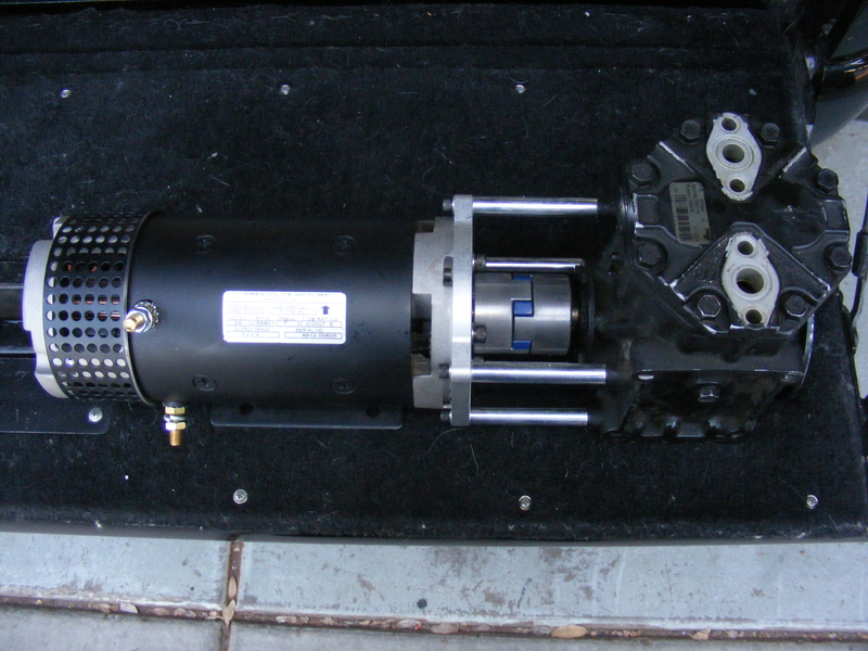
Other things going on right now: Rebuilt PS gear ported for hydro assist (not yet installed), 1.75" hydro assist ram (will be installed when I install the rebuilt PS gear), new PS reservoir with machined base (base complete, just need to weld it all together, then I will install it, and the rebuilt PS gear), electric motor-driven York compressor OBA (teaser pic below), 240 amp Leece Neville AVI160 Big-Rig alternator (to run electric OBA), HE351VE variable geometry turbocharger with 6.7 Cummins round-port exhaust manifold which will be controlled via CAN bus by an ARM Cortex-based Arduino Due. All of the stuff I just listed is stuff I already have and is in various states of completion. I eventually plan to have the Arduino run a servo-controlled AFC as well so the engine will still be mechanically injected but electronically tunable.

Teaser pic of OBA:

r-DSCF3274-2.JPG


One, in the front, with a locker. That's where all the weight is anyway, right? :eek

Meh, don't even have t-case shifters built yet. I'm waiting for non-swamp-ass weather to work on that part. I need to get the steering and new turbo on there first.
 

SuperBuickGuy

Well-Known Member
Messages
3,403
Location
Woodinville, WA
I love my York OBA. Did you do the plug-modification to keep the oil in the case? On mine, by accident, I found that having a vent-to-atmosphere and the plug modification made the oil/air separator pretty much unneeded weight.

with the hydro assist - are you going to run a steering stabilizer too?
 

MaxPF

AGNTSA
Messages
1,394
Location
The dark side of the globe
I love my York OBA. Did you do the plug-modification to keep the oil in the case? On mine, by accident, I found that having a vent-to-atmosphere and the plug modification made the oil/air separator pretty much unneeded weight.

Yup.Oil port plugged. The compressor in that pic is half worn out. It was simply used to test the entire assembly. I will get a new Omega or TCCI compressor and do the port plug mod for the actual unit that will go in the truck.

with the hydro assist - are you going to run a steering stabilizer too?
Not initially. If it turns out I need one I will add it later. Experience seems to indicate that most rigs don't need a stabilizer with a hydro assist ram. Heck, I'm not running one now.
 

MaxPF

AGNTSA
Messages
1,394
Location
The dark side of the globe
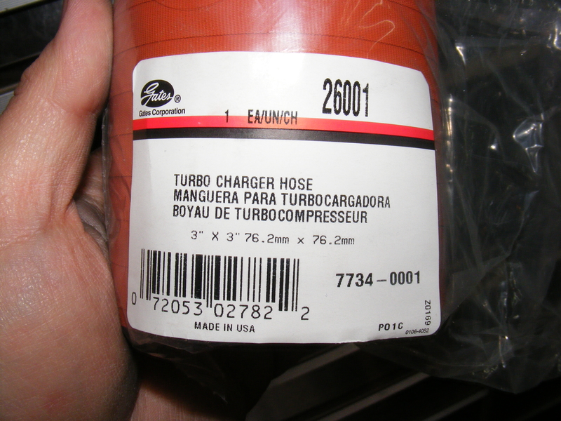
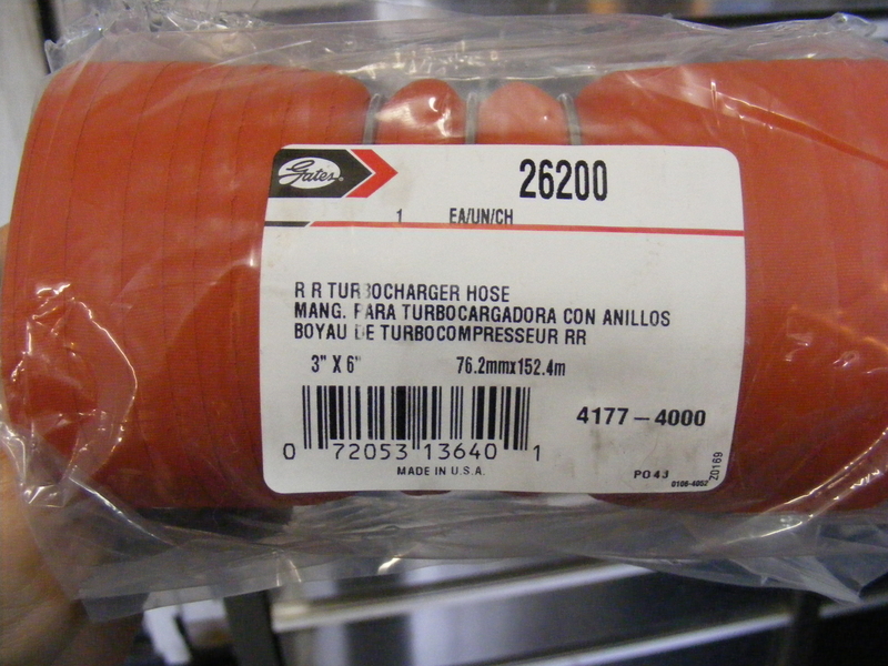
Since the exhaust was now good to go, I needed some intake plumbing. I was leery of all the Chinese silicone couplers out there, so I opted for Gates couplers used for MD/HD trucks and equipment. I got simple straight couplers that I could cut to length for areas where little flex was needed:

r-DSCF3227-1.JPG


I also needed one flexible coupling on each side, so I got a pair of ring-retained hump hoses:

r-DSCF3228-1.JPG


Note the "Made In USA" on the hoses :metal: I also got some constant-tension t-bolt clamps to retain the hoses.

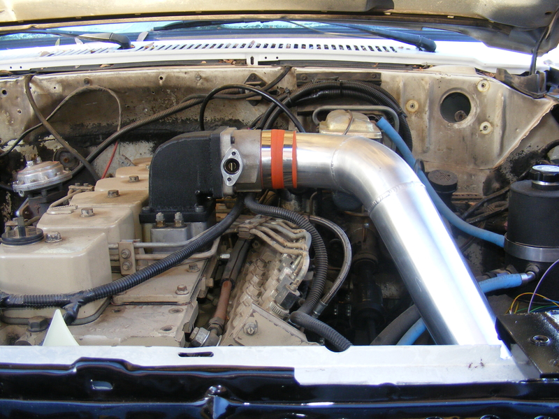
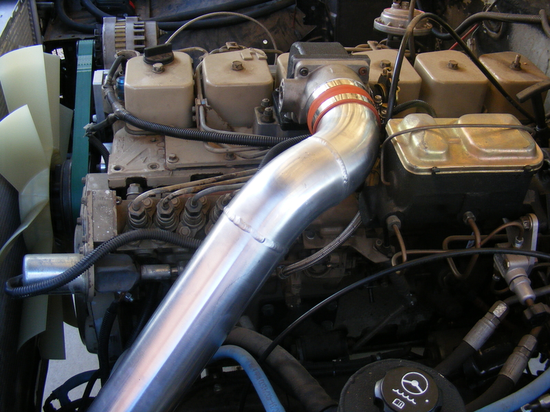
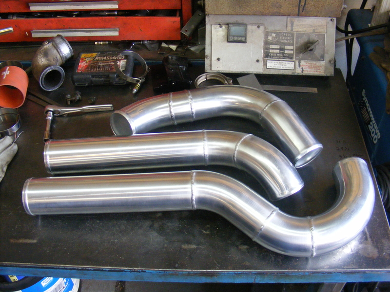
I also needed tubing. Some of the stuff I found was ridiculously expensive. I ended up using Chinese aluminum u-bends because I could actually afford them. I made a simple bead tool to put a bead on the ends, and after some cuss.gif, :hack:, :grind:, and :weld: I ended up with these:
r-DSCF3229-1.JPG


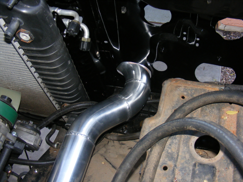
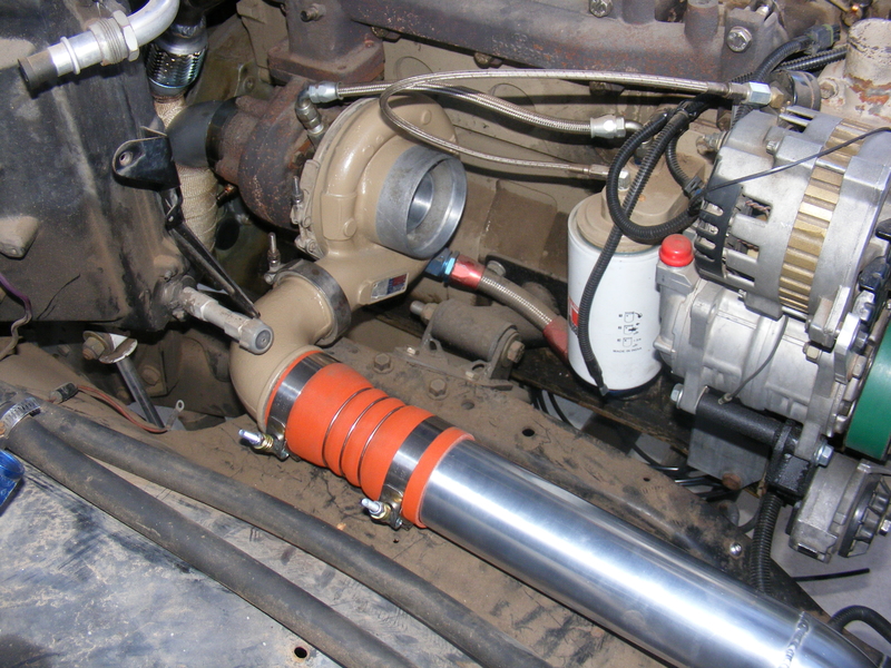
Starting at the turbo:

r-DSCF3234-1.JPG


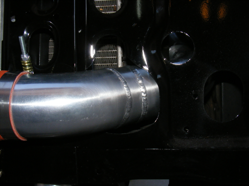
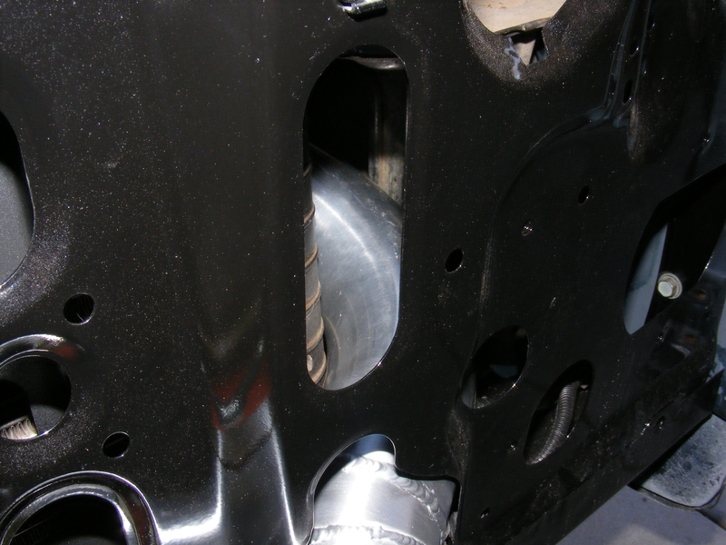
Through the core support:

r-DSCF3235-1.JPG


r-DSCF3237-1.JPG


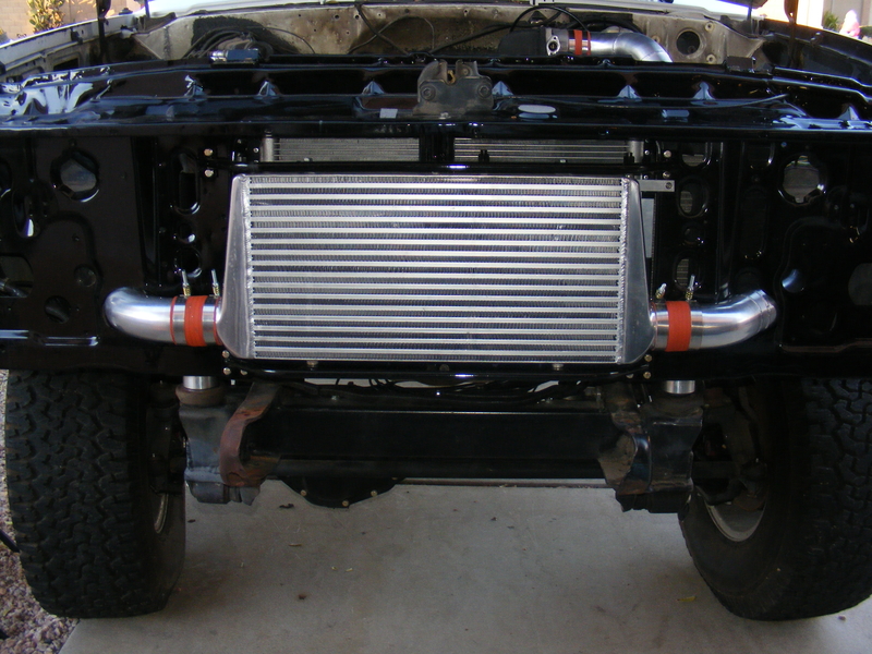
Into and out of the intercooler:

r-DSCF3236-1.JPG


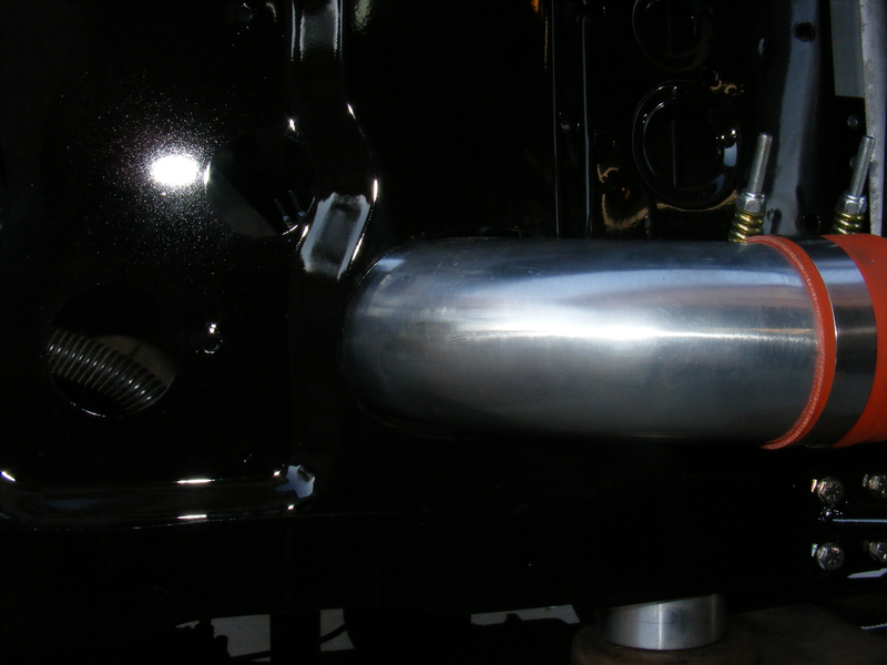
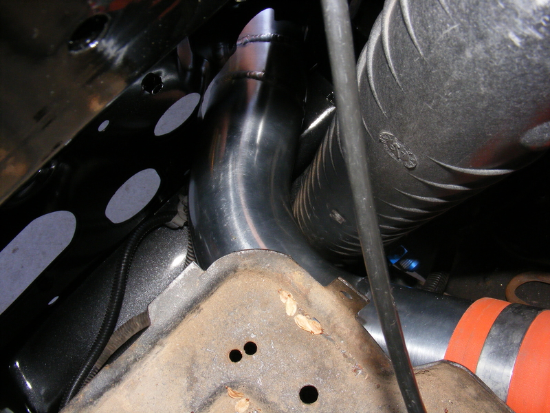
Back through the core support:

r-DSCF3238-1.JPG


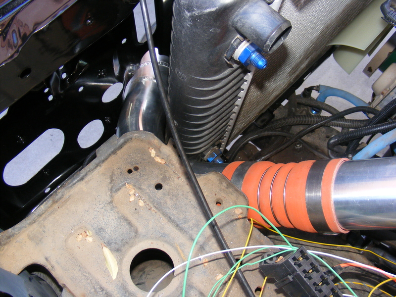
Around the extra-wide diesel radiator, which other swappers assured me COULD NOT be done:

r-DSCF3239-1.JPG


r-DSCF3232-1.JPG


A hump hose mid-pipe:

r-DSCF3231-1.JPG


And finally into the intake elbow:

r-DSCF3233-1.JPG


I had to use regular hose clamps here because the constant tension clamps were too wide. In case your wondering, yes, it does clear the master cylinder. Barely:

r-DSCF3230-1.JPG


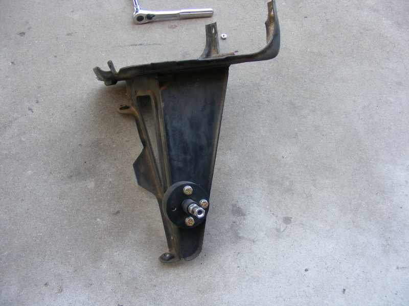
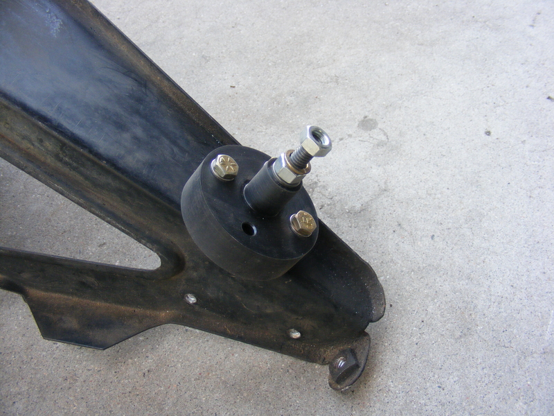
There was one other minor thing I wanted before I threw the batteries in and took it for a spin. I wanted a place to tee both positive battery cables off to the starter. A piece of Delrin, a 3/8" Allen bolt, and an hour of lathe time later yielded this:

r-DSCF3240-1.JPG


r-DSCF3241-1.JPG


It's mounted to the front of the drivers side battery tray stand. Following that was some uninteresting and still unfinished wiring and installation of the air cleaner (which I lost the pics to somewhere :( ), and it was ready to drive! Yay! So, how did that go? Stay tuned to find out...
 

MaxPF

AGNTSA
Messages
1,394
Location
The dark side of the globe
So, the initial drive showed a few issues. Most were simple fixes of minor things, but one major problem was a random failure to crank. I had a starter relay mounted on the fender. and from that relay a 14 gauge wire snaked down to the starter along the main battery cable, a distance of perhaps 7-8 feet total. It seems this length of 14 gauge had too much resistance and gave marginal voltage at the starter solenoid terminal as well as some heating of the wire.

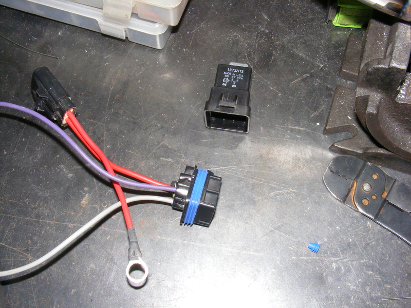
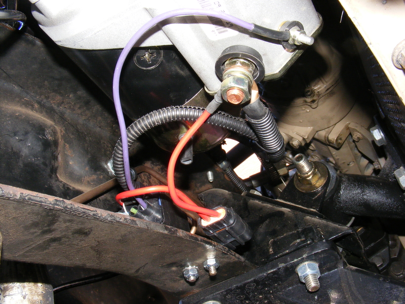
The immediate idea for a solution was to run a larger wire, but that meant threading a 12 or 10 gauge wire through an already-mounted loom. Instead, I close to eliminate the relay from the fender and connect the ignition switch start wire directly to the wire going to the starter. I then moved the relay to the frame rail adjacent to the starter, and used the starter wire going to the starter to instead actuate the relay. The relay switches power directly from the main battery terminal on the starter, protected with an inline fuse, to the solenoid terminal when the key is in the start position. The wire on the fuse holder is 12 gauge, while the other wire is 14 gauge. Since resistance increases with length, and the wires are kept very short with this arrangement, there have been no more failure-to-crank issues. Here's some pics before I put convolure tubing over all the wires:

r-DSCF3242-1.JPG


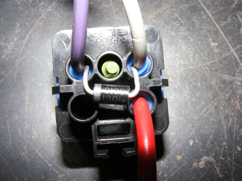
I put a reverse-biased 50V Schottky diode between the starter wire and the ground wire. When the relay opens, the energy stored in the magnetic field of the solenoid has to go somewhere. Normally, it arcs across the relay terminals as they open, which will eventually cause the relay to fail. The diode allows the reverse current to travel harmlessly to ground with no arcing, where it is dissipated as heat in the solenoid winding.

r-DSCF3243-1.JPG


Here's the installed relay and fuse:

r-DSCF3246-1.JPG


This setup engages the solenoid without fail, even when the batteries are too weak to give more than a half-crank to the engine. The weak batteries were caused by my alternator losing a diode, which is a story for later time ;).
 

MaxPF

AGNTSA
Messages
1,394
Location
The dark side of the globe
Quite a bit has happened since the last update. I have been chasing an intermittent bump-induced driveshaft vibration for several months. Despite rebuilding the CV and replacing the output bearings in the t-case the vibration persists. :gaah: I will get it figured out one of these days.

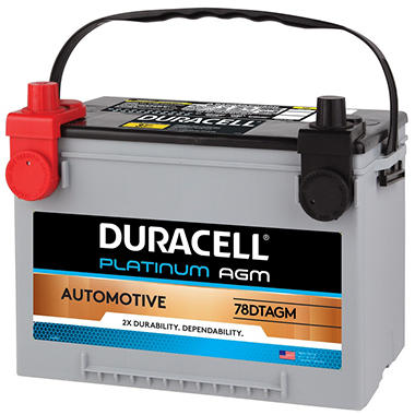
My batteries finally went Tango Uniform I was originally set on running a pair of group 24 flooded deep cycles because, frankly, I believe properly maintained QUALITY deep cycles will outlast AGMs. However, that plan got thwarted when I discovered that Sam's Club had group 34/78 Deka AGMs (labeled Duracell) for only $105 during a Christmas sale!

0008399630000_A


Sign me up on that deal! I eventualy plan on moving the batteries out of the engine bay and into the rear of the truck, so hopefully getting them out of the engine bay heat will increase their lifespan. When I do that I will make the battery boxes capable of accepting group 31's.

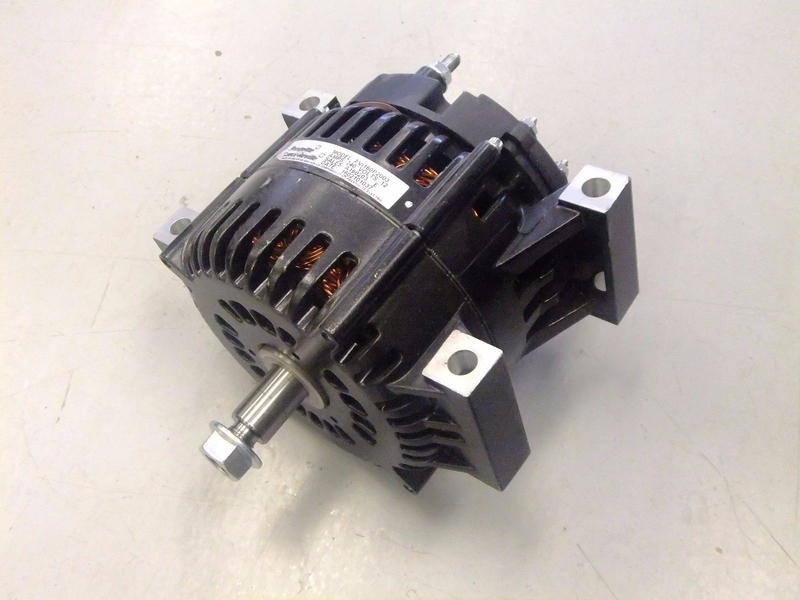
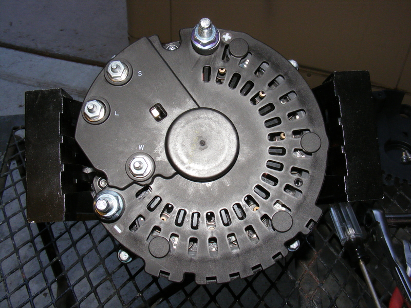
Not long after that my third Autozone alternator decided to windmill the pulley and spit the belt off. Swell. At this point my option was to fix the pulley and keep running the Zoner alternator, or put this in it's place:

r-s-l1606.JPG


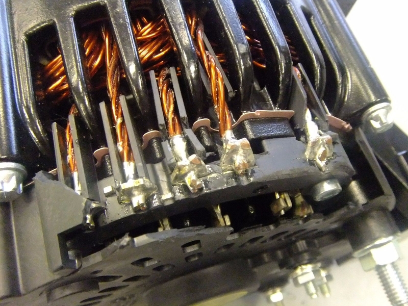
I scored a pair of these off of Ebay for $165 each. Normally, these are $525 alternators, but these had been dropped and had broken back covers and some dings, hence the discount.

r-s-l1600.JPG


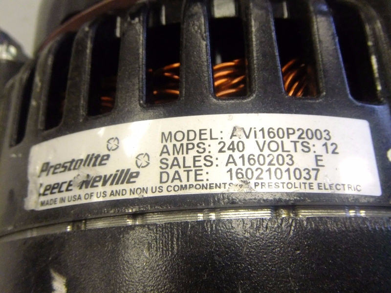
$525 you say?!?! Why so expensive? Simple answer:

r-s-l1608.JPG


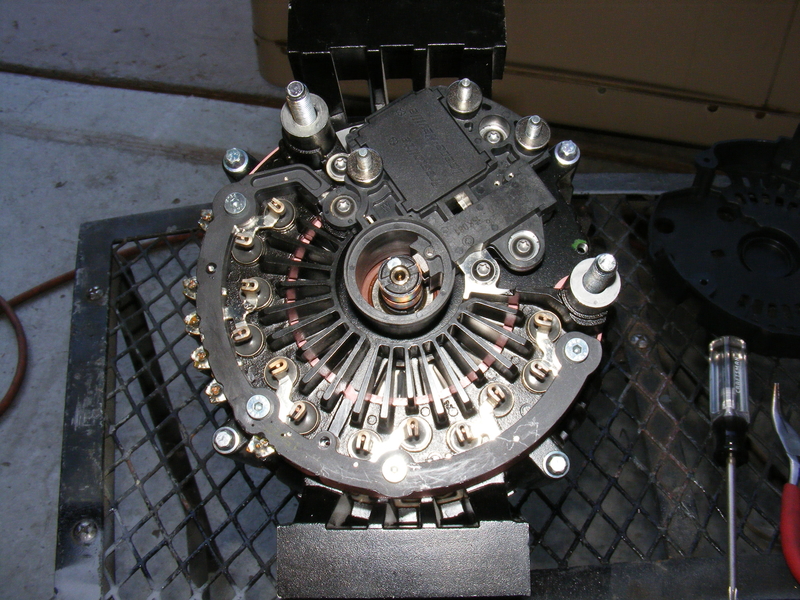
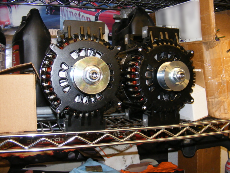
This alternator can crank out 240A CONTINUOUSLY. And they are made in USA. Unlike mere mortal alternators that have six rectifier diodes that are heat-sinked to the case, these bad boys sport 12 rectifiers in their own heat sink, which is still mounted to the case for further head sinking.It also has dual fans:

r-DSCF3315.JPG


I ordered new rear covers for them, as well as an 8 rib pulley and a 7 rib pulley. They 8 rib pulley is for mine, while the 7 rib pulley is destined for Todd's Jeep. These alternators have 7/8" shafts, and it seems 6 rib alternators are not made for that size shaft, so the 7 rib jobbie will be used on the LS motor with it's 6 rib belt. Here they are, ready to go:

r-DSCF3316.JPG


r-DSCF3317.JPG


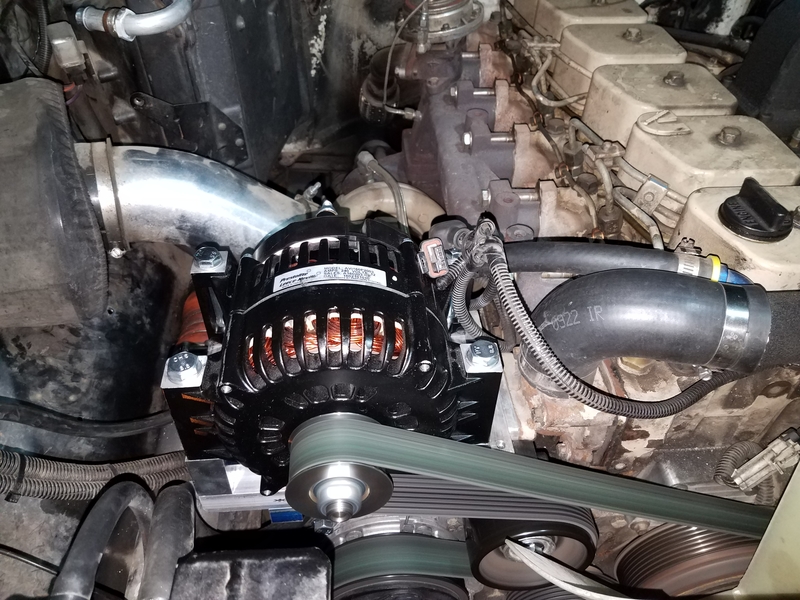
10 hours of machining and wrenching later, I ended up with this:

r-20170129_190404.JPG


What is not noticeable in the above pic is that the AC hoses and lines are gone. This was pre-planned even before the alternator debacle. I evacuated the refrigerant and capped the compressor, condenser, and receiver. In the next few days I will remove the glower/evaporator box from under the hood and the HVAC box from under the dash. This will get replaced by a unit that fits entirely under the dash. The purpose of removing the factory HVAC stuff is to make the room needed to fit the HE351VE variable geometry turbo that I have acquired :) Not to mention I have always disliked that crap cluttering the engine bay. It will also make room for another item I have just ordered, but I am keeping hush-hush for now :cool:
 

MaxPF

AGNTSA
Messages
1,394
Location
The dark side of the globe
But wait! There's more! Another item on the to-do list for the New Year was new tires.

I had originally intended on running the same 37" BFG KO2's that Todd is running on his Jeep. However, perusal of the reviews on this tire revealed a disturbing trend; it seems they wear rapidly when they are on a heavy vehicle. I had already noticed the weight on the front end of my truck has not been kind to the 35" KO's I was running, and I most certainly did not want to pay $1500 for tires that would only last 20,000 miles. :whaa:

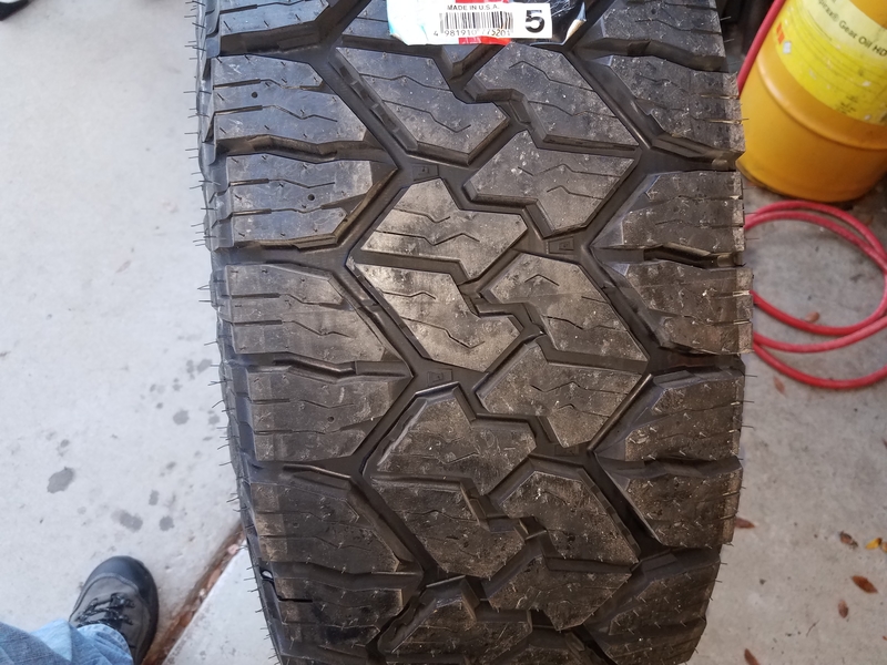
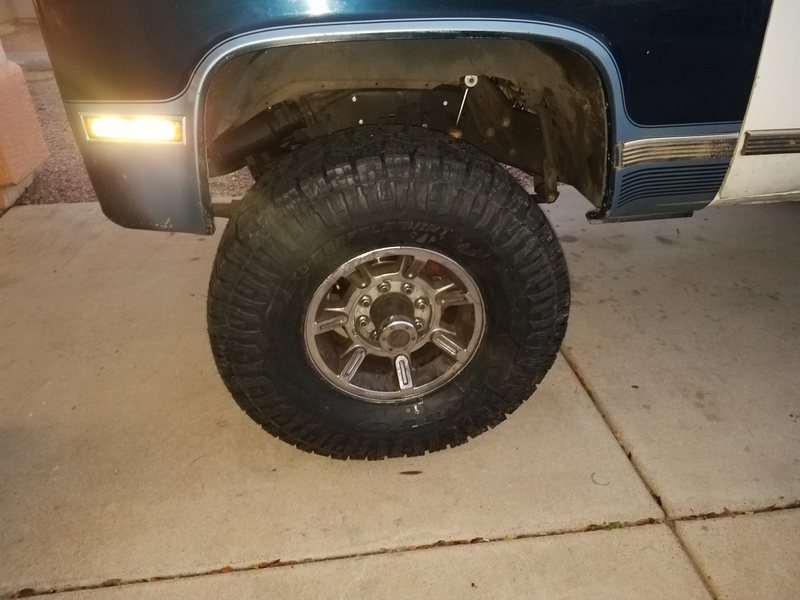
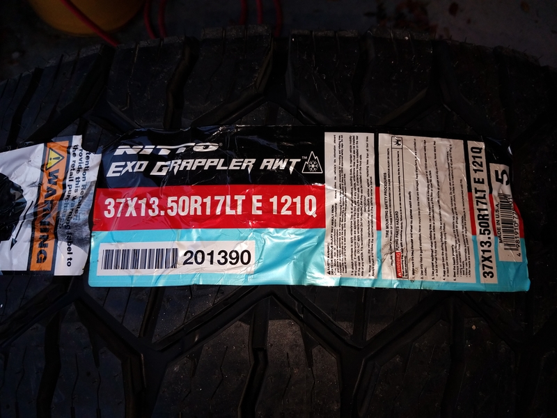
A buddy of mine with a Cummins-swapped old-school Suburban had the same issues with KO's and ended up switching to Toyo M55's. The M55's are designed for heavy trucks that routinely run down unpaved roads, so they are tough and designed to wear well. My buddy has been running them for over three years and has nothing but praise, so I was sold. Sadly, the biggest size available is 33" and I want 37's :( So, I did some more looking. As it turns out, Toyo's sister company Nitto recently introduced a new tire geared toward the same type of use as the M55. It is called the Exo Grappler AWT, and unlike the M55 it is available in a 37" version. 37x13.5x17 to be exact, so it is an inch wider than the typical 37" radial. It's E load rated, and guys running them on 3/4 and 1 ton trucks report 30,000+ miles with plenty of tread left. And, they only cost $15 more per tire vs the BFG's. Sounds good to me, so I had Discount order a set of four. They arrived in due course, and looked better in person than on Nitto's web page:
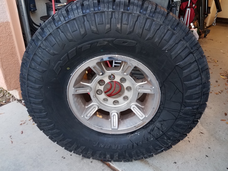
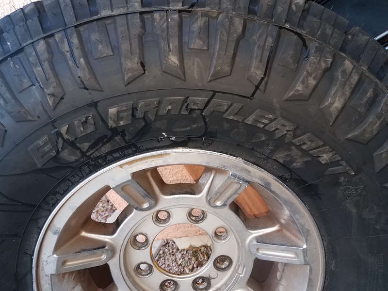
r-20170121_172422.jpg


Mounted on my H2 rims:

r-20170121_172416.jpg


r-20170121_172443.jpg


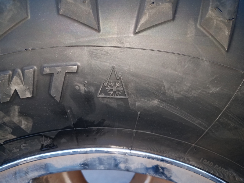
Like the KO2's, the Exo's are severe snow service rated, which will come in handy during those December hunts when a snow storm rolls in:

r-20170121_172457.jpg


Here's the tread:

r-20170121_172409.jpg


And finally, installed on the truck:

r-20170121_180205.jpg


So far I have put about 100 miles on them, and they are night and day compared the the 35" KO's they replaced. They are responsive, and despite their E load rating they soak up the road bumps better than the BFG's they replaced. They are also smoooooth, which I attribute both to the quality of the tire and the 10oz of Dynabeads in each tire instead of conventional balancing. It will be interesting to get them off-road and see how they work and how they wear, but so far I like 'em a lot.

One side benefit is that the 37" tire actually improves my gearing. The engine seems happier cruising down the freeway, and I no longer need 5th gear on the surface streets. It will be interesting to see if/how much my fuel economy is impacted by the new rubber.
 

CaseyS

Well-Known Member
Messages
755
Location
Louisiana
So that's 4.10 gearing with 37s and 0.73 overdrive? Should be just about right. How does the gearing feel?
 

MaxPF

AGNTSA
Messages
1,394
Location
The dark side of the globe
It started out so simple; one of the straps retaining my rear u-joint had light between the strap and the u-joint cap. I have been chasing an intermittent bump-induced driveshaft vibe for months now, so I figured I may as well check out/fix the strap to make sure the cap isn't walking around in the yoke. Easy job, which should have taken no more than 30 minutes.

You want to know how to make God laugh? Tell Him your plans :giggle:

So I pull the bolts retaining the straps. Now, having had them on and off a few times, and using Loctite each time, means the threads were gummed up. No biggie, I had a 6mm tap hot and ready to go. Oops... turns out they are 8mm, not 6. And I don't have an 8mm tap (mental note: add 8mm tap to my next MSC order). Fortunately, I DO have a set of Snap-On thread chasers, so I'm still in business. I throw the straps and bolts in a paint mixing cup and add a little acetone to degrease and de-Loctite the parts, then I crawl under the truck with the thread chaser and a 1/4" drive ratchet. I get about half way in, and I can feel the thread chaser getting mired in the goo. I back it out, clean it off, and run it back in. It's still gooey, so I lean on it a bit. Did I mention I'm using a 1/4" drive ratchet? There's only so much torque a mere mortal can apply to a 1/4" drive ratchet, and it ain't much. One moment I'm removing Loctite goo, and the next moment the ratchet suddenly spins really easy. Didn't even make a sound, just twisted the shank of the Snap-On thread chaser clean off. Using a 1/4" drive ratchet. Did I mention that part? :banghead: Now, I have seen my share of broken $#!t, so I noticed two things. Snap-On's Sooper-Dooper thread chasers are maybe grade 8. They felt more like grade 5 when it broke. They are definitely not any kind of tool steel. Second, the shank could have been much larger. It was only maybe 1/4" diameter or so.

So there I sat, junk in one hand and a broken thread chaser in the other. And, of course, the rest of the chaser stuck in the yoke, which is firmly bolted to the pinion in my rear axle. Swell. Imake a phone call to my buddy Todd, who just happens to own a machine shop, and after a bout of laughter on his end he says that there are no jobs set up on the manual mill. Cool beans, I'm in business! I figure I will pop the yoke off, drill out the busted thread chaser, and while I'm at it I will machine the yoke to use u-bolts instead of the crappy straps. I bust out the 1/2" drive impact and a suitable socket buzz the yoke nut off, and try to slide the yoke off the pinion. It doesn't budge. I get on it with a plastic-faced hammer and it still doesn't move. Interference-fit splines. Swell.

Not a problem, I figure. My rear axle happens to be an AAM 14BFF, which has a drop-out pinion support. I zap out the 6 bolts holding the pinion support, tap it with the plastic hammer, and it slides right out. I jump in a borrowed beater and make haste to the shop. Ended up having to use a press to get the yoke off the pinion. Oh yeah, this will be a ball of laughs to re-assemble. I put that out of my mind as I examine the off seal arrangement AAM uses on these later model axles. Apparently, they really, REALLY don't want them to leak. I press off the dust cap and something that looks like a thick speedi-sleeve with an integral outer seal so I can machine the yoke. A carbide drill bit made quick work out of the broken thread chaser, after which I drilled out the holes to .394" for the 3/8" u-bolts. Then another half-hour of machining with a .750" end mill and the yoke was ready to go.

Now comes the fun part. I go to put it back together only to find out that the outer pinion bearing doesn't want to slip over the pinion shaft. WTF?!?! I fuss with it some more, and bigger than $#!t I manage to pop the garter spring off the seal :gaah: WTF, is Mercury in retrograde or something? Of course, there is no way to re-install the spring with the seal in place, so I say eff it and remove the seal. At least now I can remove the outer pinion bearing from the support assembly and see what the deal is. Simple answer: it is a light PRESS FIT onto the pinion shaft! :banghead::banghead::banghead: By this time I am swearing a littany of curses at the engineer who took a perfectly good design (the original GM 14BFF) and decided to "improve" upon it.

Since I don't have a shop manual for this new "improved" 14b, experience tells me that I will have to heat the bearing to 250°F and slip it down until it seats against the crush sleeve, then install the new seal, then heat the yoke to 250°F and tap it in place against the bearing. Then I can install the new nut and set preload. Nice. Now all I need is a new seal, since I destroyed the old one removing it. At least they don't appear to be too expensive.
 

MaxPF

AGNTSA
Messages
1,394
Location
The dark side of the globe
The seal will handle 250°F no problem. Turns out it wasn't necessary though. A little creativity allowed me to press it on using the yoke nut.

Looks like my memory was faulty. According to my 1991 shop manual,the 14b axles have always had press-fit outer pinion bearings. It was every but as much fun to assemble as I hoped it would be.
suicide.gif


Cliff notes for those who have assembled D60', D70's, 10b's, and 14bsf; if you think the crush sleeves on these axles are a bish to compress, you haven't had the pleasure of working on a 14bff. Now granted, Snap-On air impacts are a bit weak-sauce compared to an Ingersoll-Rand unit, but mine (1/2" drive) has always been able to crush D60, D70, 10b, and 14bsf sleeves. The brand new sleeve in the 14bff just laughed at it. I ended up having to break out the 3/4" long-handle ratchet with a cheater bar and reef on it for a half hour to get it crushed to the specified preload. This thing was a stone bich that I have no desire to repeat. IF I have to do another one in the future I guarantee I will pre-crush the sleeve in a press to within .020" of final length to safe a lot of grief. Or, borrow a 3/4" drive impact.

Anyway, got it running now. I'm hoping it fixes the vibe problem, but I'm not holding my breath...
 

MaxPF

AGNTSA
Messages
1,394
Location
The dark side of the globe
Back when I replaced my pitiful Zoner alternator with a real alternator, I also mentioned that I had removed my AC blower/evaporator stuff from the engine compartment as well as the stock under-dash AC crap. This is getting replaced with a system that will fit entirely under the dash. Of course, I could have bought a system from Classic Air or Vintage air, but that wouldn't have been any fun. Besides, I wasn't really happy with their stuff. That being the case, I elected to roll my own.

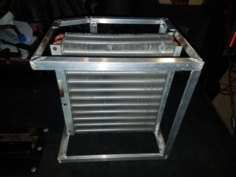
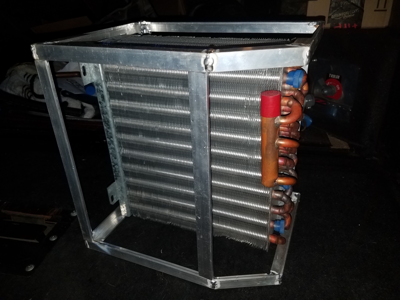
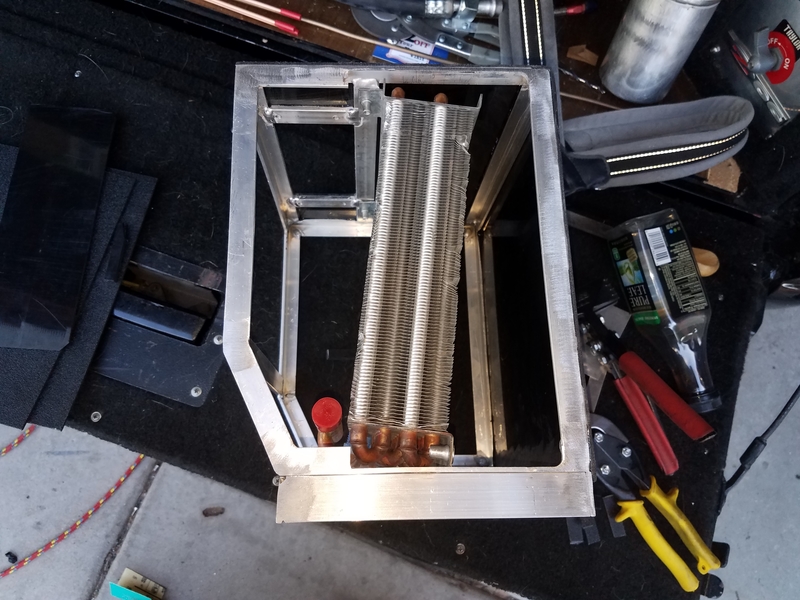
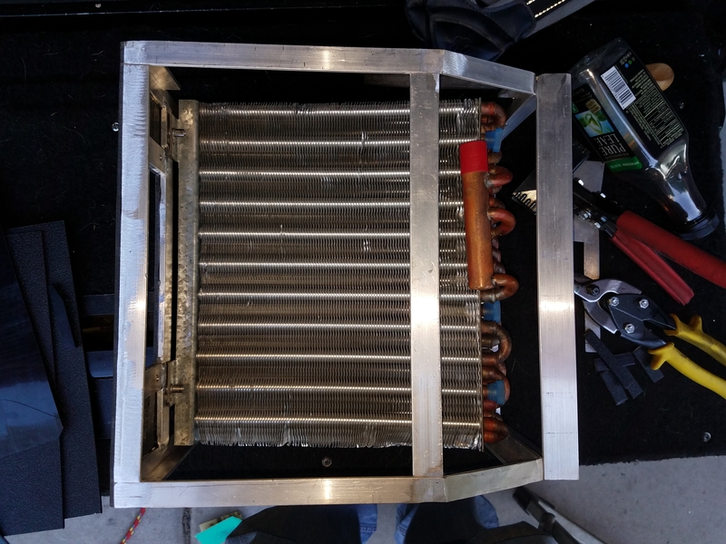
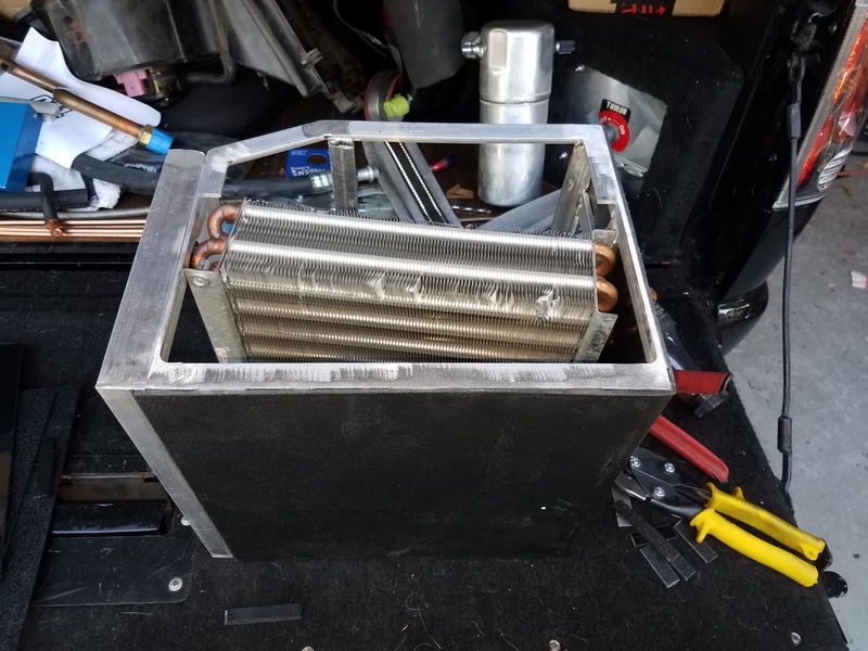
One of the things I didn't care for with the Classic and Vintage systems was the meager evaporator size of these units. I got an evaporator from a mid-2000's Navistar application that was the right size, but needed some plumbing mods. I cut off most of the suction pipe and un-brazed the distributor tubes from the core, and then after much measuring and thinking I built an aluminum skeleton for the evap housing:

r-20170310_184353.jpg


r-20170310_184422.jpg


This part fits where the glove compartment resides, with the side with the beveled edge going against the firewall. It will be entirely enclosed with ABS. The blower will blow the air into the back perpendicular to the flow through the core. The air will then flow 90° through the core before changing direction 90° again and flowing out through the side. This will be easier to see once the enclosure is completed. At that point the air will enter a separate, attached enclosure that will house the heater core and the various doors and duct outlets.

Because I wanted the engine bay as free of clutter as possible AND I wanted my AC to be as efficient as possible, I chose to use a thermal expansion valve (TXV) instead of a simple orifice tube. This eliminates the accumulator, which would have to go under the hood on the firewall, and provides actual refrigerant control. Back in the good ol' days, automotive TXV's were made by outfits like Parker and Alco, who also made TXV's for stationary AC and refrigeration. However, they were simple, rudimentary designs built to a price point. Nowandays, all automotive TXV's are made in China, and the quality and reliability has gone down. While they get the basic job done, they tend to be quite variable from sample to sample and they usually "hunt" badly at low evaporator load (i.e. when the blower is on low speed), alternating between starving and flooding the evaporator. Sometimes the flooding is severe enough that liquid refrigerant makes it back to the compressor. At high loads they often run somewhat starved, with resulting high superheat and less than stellar vent temps. Knowing this, I chose to use a real AC/refrigeration TXV from an American manufacturer.

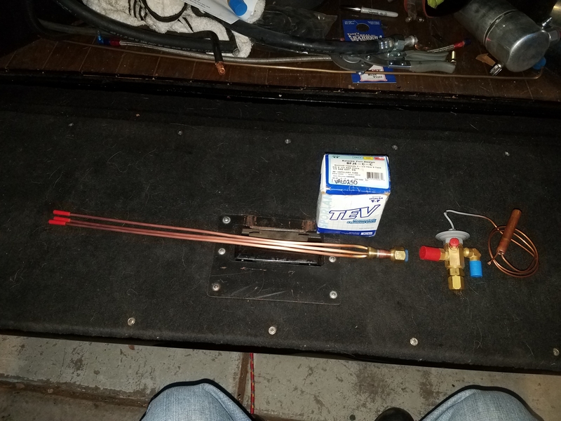
The distributor that came on this coil was designed for an automotive TXV with an o-ring sealed output, while the Sporlan TXV I am using has SAE flare fittings. That combined with the fact that the stock distributor was in the wrong physical location for my needs and not easy to relocate is why I removed it and it;s tubes. Because there are so many different configurations of distributors they are not something that HVACR wholesalers typically stock. Fortunately, I found a seller of surplus NOS parts that had a distributor from a Rheem R-22 heat pump of a suitable size with suitable feed tubes already brazed on, and it was cheap. When I got it, it turned out that the distributor was a Sporlan branded part. Cool! The feed tubes were 3/16", which are a bit smallish for an R-134a system, but the Sporlan software tool showed the pressure drop to be acceptable for my overall system design. I went ahead and brazed a 1/2" SAE flare fitting to the distributor inlet for attachment to the valve. Here's the TXV and distributor assembly, ready to be brazed/assembled onto the evaporator once I figure out exactly where I want to put it:

r-20170310_184541.jpg


When I pulled the OE HVAC unit out of my truck I salvaged the heater core from it. I had replaced it several years ago, and because I rigorously maintain my cooling system it was still in excellent shape. Well, excellent shape other than the somewhat crushed tubes that happened while I was trying to remove the heater hoses :mad: Still, the tubes are easy enough to straighten out if I so choose. I also got a new all-aluminum heater core. I am still undecided as to which core I want to use. The aluminum core is obviously more restrictive to airflow compared to the copper/brass unit, while the copper/brass unit has the disadvantage when it comes to transferring the Cummins' meager engine heat to the air flowing through it. If I was running a gas engine with a 195° thermostat the choice would be easy, but with the Cummins' 180° thermostat and limited waste heat production I am leaning toward the aluminum jobbie.
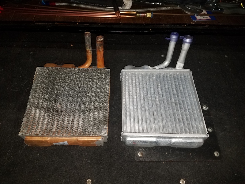
r-20170310_184642.jpg


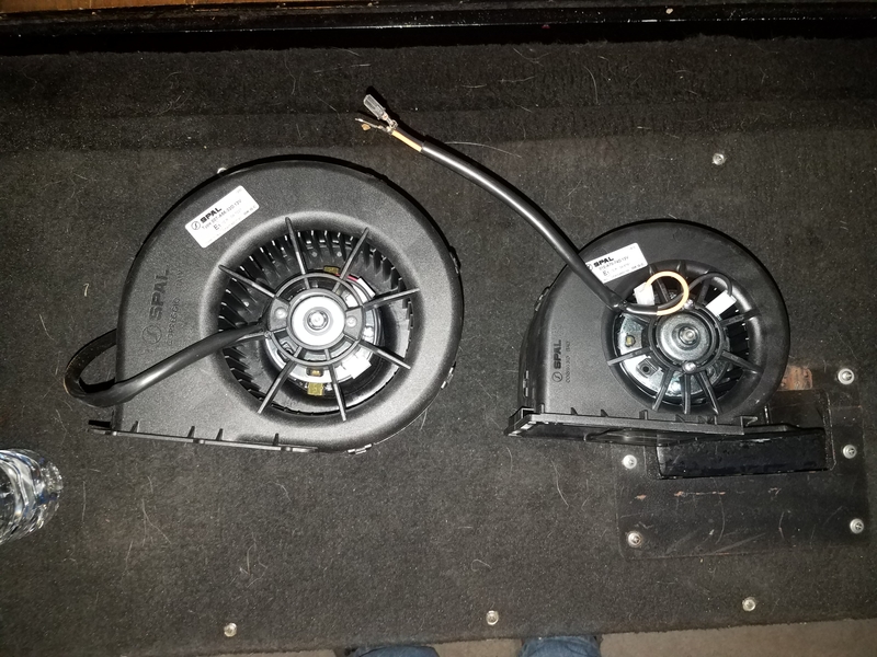
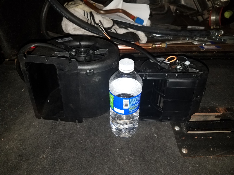
Finally, there is the blower. Here, the choice of manufacturer was easy. In the pic below you can see two blowers. The smaller one is the one that Classic and Vintage use in their units. The big sumb***h is the one I am going to use! I figure I have the space to fit it, and I can always limit the speed of the big blower whereas I can't add more speed to the small one. Plus, for a given airflow the bigger blower is quieter.

r-20170310_184729.jpg


r-20170310_184741.jpg


That's it for now. Stay tuned as the AC-from-scratch adventure continues!
 

MaxPF

AGNTSA
Messages
1,394
Location
The dark side of the globe
Still working on the evaporator housing. I made a few mods to the initial design. I found that mounting the evaporator at a slight angle gave an increase in room behind the evaporator for the expansion valve without reducing the outlet area, which is A Good Thing™:

r-20170318_165912.jpg


Here's a view of the firewall side. On the bottom, which is actually the left side if you were viewing it installed in the cab, you can see the outlet extension. This is what the housing containing the heater core and distribution doors will slide onto:

r-20170318_165924.jpg


Top view. You can see that I already have ABS glued to the front and right side:

r-20170318_165932.jpg


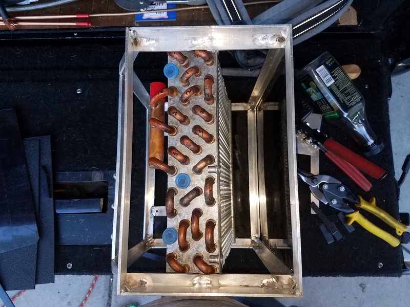
This is a view looking into the outlet extension. The face of the evaporator on the right is the outlet. The end of the evaporator will be covered by more ABS and will be on the inlet side. The little blue caps cover the open tubes where the three distributor tubes will eventually be brazed. The black crud in the corner welds is where I dipped the tungsten into the weld puddle because I was welding by sense of smell at that point :sigh: I have discovered that welding is a perishable skill. If you don't do it often you lose the muscle memory and your skills deteriorate. Unfortunately, so does your eyesight as you age. My welding skills, especially on aluminum, used to be MUCH better than they are now.

r-20170318_165949.jpg


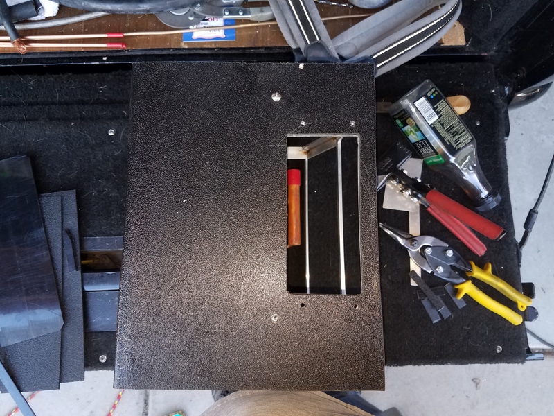
This is the right side. The square hole is where the blower blows into the housing:

r-20170318_165959.jpg


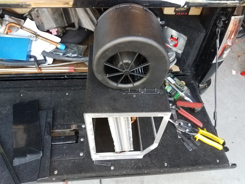
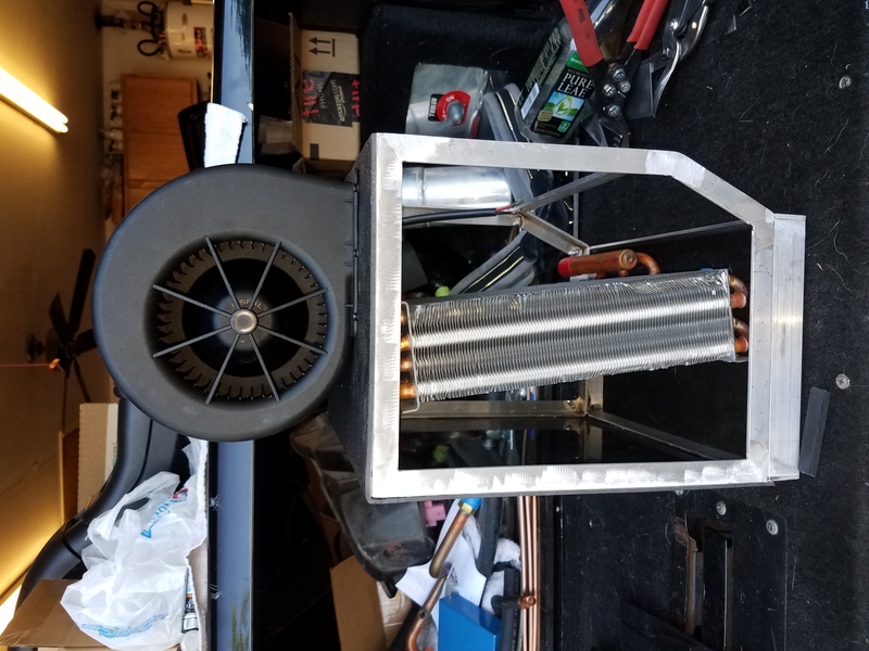
What it looks like with the blower in place:

r-20170318_170017.jpg


r-20170318_170026.jpg


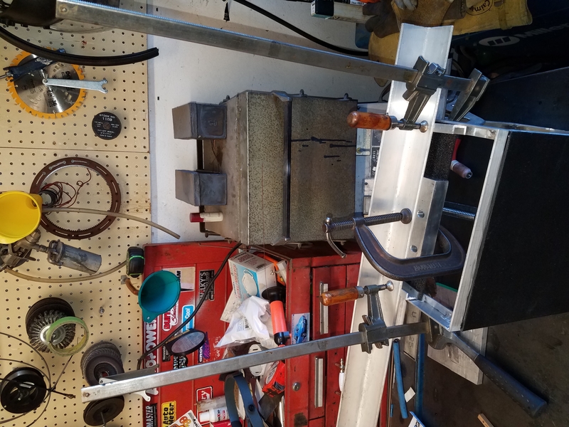
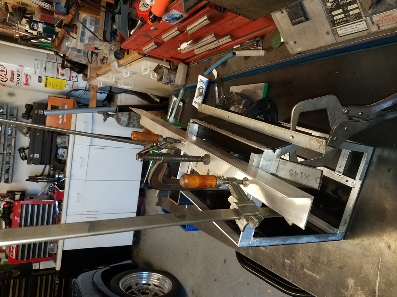
I now reached the point where I needed to glue two more ABS panels on before I can proceed further, so as of tonight it is sitting with panels clamped in place letting the adhesive fully cure overnight:

r-20170318_175146.jpg


r-20170318_175159.jpg


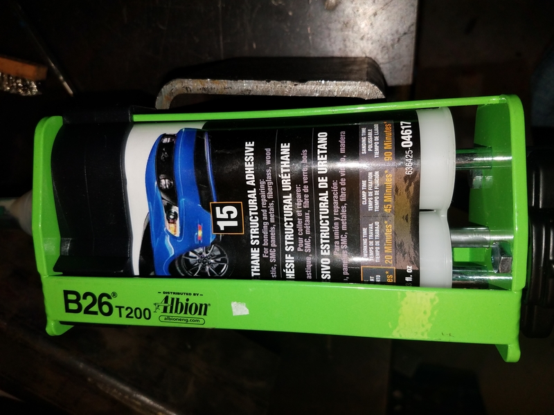
This is the adhesive I am using. The place I buy from has a good assortment of products by 3M, Norton, and SEM. Of the products, this one was recommended by the manufacturers literature for bonding metal to metal, metal to plastic, and plastic to plastic. It's a 2-part urethane adhesive. It's not as strong as the epoxies, but the epoxies weren't recommended for use on plastic:

r-20170318_185233.jpg


After I glued the first panel on and let it cure overnight I tried to rip the glued seam apart and it just laughed at me, so I think it is strong enough for an AC housing :thumbs: I also got a tube of moisture-curing urethane seam sealer for sealing gaps and especially for sealing the condensate tray. It's half the price fo the two-part urethane adhesive and thicker. I don't want air leaks, and I really don't want a condensate leak!

That's it for now. Stay tuned for the next exiting episode!
 

SuperBuickGuy

Well-Known Member
Messages
3,403
Location
Woodinville, WA
excellent timing on this - I'm in the midst of a roll-my-own ac system for my 'burb. I like what you're doing - a lot. The roll-my-own portion is divorcing the rear ac system from the front and using an electric pump for the back that I can plug in to house power when camping (a portable generator), and not having anything on the roof but still be able to run when I'm going down the road off an inverter.
 
Top